I. "Socket Bayonet" Terms
By SABC founder, Robert M. Reilly, American Socket Bayonets

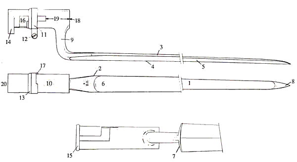
| 1 - Blade 2 - Blade shoulder 3 - Edge 4 - Back edge 5 - Back flutes 6 - Face flute 7 - Base guard |
8 - Point 9 - Shank (a.k.a. "Elbow" or "Neck'7) 10 - Socket 11 - Locking ring (a.k.a. "Clamping band" or "Clasp") |
12 - Locking ring screw 13 - Locking ring shoulder 14 - Bridge 15 - Reinforcing collar 16 - Mortise (a.k.a. "Zig Zag') |
17 - Locking ring stop pin 18 - Bore 19 - Muzzle 20 - Butt |

PROPER DIMENSIONING OF THE
SOCKET BAYONET
In order to establish some basis for consistency in determining
the various important dimensions of the socket bayonet, there are a
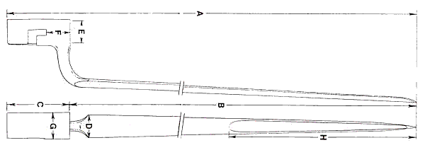
number of things which should be kept in mind. The accompanying illustration
provides the basis for properly taking these measurements.
The overall length of the piece (A) will be a combination of the socket length (C) and that of the blade (B). Note that the blade length is measured from the front of the socket to the tip of the point. This may seem logical in most instances, but there may be times, particularly with regard to those bayonets with base guards which are normally positioned well forward of the socket face, such as some Enfield or Brown Bess types, where it might seem more sensible to take this dimension from the point to the shoulder. Perhaps - but with the thought of consistency in mind, it is recommended that this measurement be taken in the same way regardless of blade configuration.As to the width of the blade, it should be measured at the widest point, normally at or just forward of the shoulder (D).
When measuring the blade's flutes, which usually begun just to the rear of the point, this dimension should be taken from the point itself to the rear of the flute (H).
One of the most important measurements on the socket bayonet is its bore diameter. In order to take this measurement accurately, an inside calipers (or better still, an inside micrometer) should be used at the front of the socket, and this setting then carefully "miked" with an accurate micrometer. A large number of bayonet, and particularly those produced during and after the Model 1855 era, are virtually identical in outward appearance, with their differences coming only in the diameter of their bore. This alone can well determine exactly which firearm to which the bayonet belongs, and should be measured with care (E). To take this measurement from the rear of the socket, incidentally, while somewhat easier to do, will be found to be far less accurate, and particularly on early types and those produced without a bridge or reinforcing collar. Virtually every bayonet tapers in bore diameter from front to rear, and those without reinforcement of any kind at the rear are often found to be eccentric in shape, making accurate measurement impossible.
Should the outside diameter of the socket be necessary (G) -which it rarely is, the measurement should be taken in that area forward of the mortise and to the rear of the shank.
Another highly significant dimension is the Muzzle length (F) -and one that is often overlooked. This is the distance from the front of the socket to the forward edge of the mortise. Since American socket bayonets were usually designed so that the front of the socket was nearly flush with the muzzle of the firearm, this dimension should coincide almost perfectly with that from the gun muzzle to the front of the bayonet stud, and may well help to bring bayonet and firearm properly together.
There are other dimensions which the collector may wish to take from his bayonets, but which have little practical value. The length and diameter of the shank might be considered one of these. Also, to a lesser extent, the thickness of the blade. On occasion the thickness and/or height of the bridge may be useful, but not as a rule.
Basically, then, concern should be centered on relatively few dimensions: socket and blade length (which combine to provide the overall length); the blade width; the bore diameter and the muzzle length. Others may be included in cases where they are significant or peculiar to the identity of a specific piece, but for the most part only those noted have been included in this work.
III. "Knife Bayonet" Terms
Used with kind permission of the author, Gary Cunningham, AMERICAN
MILITARY BAYONETS OF THE 20th CENTURY
NOMENCLATURE OF THE KNIFE BAYONET
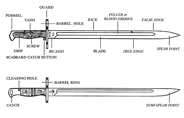
The bayonets below are drawn in an orientation that is standard among collectors. The point is to the right and the true edge is down. The side seen is the Obverse side, the opposite is the Reverse side. Markings are described as to location, such as Obverse Ricasso, and in the direction that they are read. Horizontal is read along the length, Inverted Horizontal is read with the edge up. Vertical is read with the point up, Inverted Vertical is read with the point down. The markings on the bayonets below would therefore be described as Vertical on the Obverse Ricasso. This is a simple method of describing marking location and direction without having to make a drawing.

BAYONET, MODEL OF 1905 (top) and MODEL OF 1917 (bottom)
The names of the parts of the bayonet vary with the model and time period. In the examples above, the names in BLOCK type are taken from the World War One manuals. The words printed in ITALICS are those used in more technical publications and commonly by collectors.
Unfortunately, names used by manuals and collectors often vary. On the Model 1905, the hole in the upper part of the guard through which the rifle barrel passes is called the barrel hole, while on the Model 1917 it is called the barrel ring. Collectors often use the term muzzle ring or guard ring. The diameter of this hole is called the bore.
The slot in the upper pommel into which the stud on the rifle upper
band slides is called the undercut groove in the Model 1905, while on
the Model 1917 it is called the stud slot. Collectors may refer to it
as the attachment groove or slot. This difference in terminology can
lead to confusion. Collectors exchanging information should make certain
they understand each other.
Since these terms are not absolutely standard, they will be defined here so when they are used in the drawings or text that follows there will be less chance of misunderstanding.The two major generic components of the KNIFE BAYONET are the BLADE and the HILT.
BLADE: Generally, the portion of the bayonet which is forward of the guard. There are several blade forms, but this guide only deals with the Knife form. The blade is divided into the:
RICASSO: The flat area immediately in front of the Guard, running from the guard to the point where the edge starts.
FULLER: One or more grooves in the blade body parallel to the back. Fullers may be Stopped or Unstopped. A stopped fuller has a distinct end which rises abruptly to the blade surface, while an unstopped one rises gradually to the level of the blade. Many people, including some military publications, refer to the fuller as the blood groove.
TRUE EDGE: The primary sharpened edge, normally on the lower side
FALSE EDGE: A sharpened edge shorter than the true edge, usually on the upper side.
DOUBLE EDGE: A blade which is sharpened about an equal amount on both edges.
BACK: The unsharpened portion of the blade opposite the True Edge.
POINT: There are names for all of the various point shapes used on knives and bayonets. Most U.S. bayonets use the SPEAR POINT where the two edges slope toward each other, meeting approximately on the center line of the blade. The Model 1905 has a traditional spear point. The Model 1917 has a SEMI-SPEAR POINT, in which the bottom line of the blade slopes more rapidlyupward, and the line of the back slopes only slightly downward. This has also been called a Modified Spear Point. Other rarely used shapes are defined with their bayonet.
HILT: Generally all parts other than the blade. In some references, the Guard is considered a third part, with the Blade being to the front of the Guard and the Hilt being to the rear of the Guard.
GUARD: A vertical piece to the immediate rear of the blade. On a knife bayonet the guard helps prevent the hand from slipping onto the blade when the bayonet is used separately as a weapon or tool. On most bayonets, a hole in the top of the guard slips over the barrel. This may be called the BARREL RING, the GUARD RING, the MUZZLE RING, or the BORE.
GRIP: Sometimes called the HANDLE, this is the area between the guard and pommel, where the bayonet can be held by the hand. This may be a solid piece, or may be removable in which case the removable pieces may be called the GRIPS or sometimes the SCALES.
TANG: The piece, usually an extension of the blade, which connects the blade and pommel.
POMMEL: The piece at the rear of the bayonet. It may have a small extension or hook at the bottom to help hold the bayonet in the hand when it is not being used on the rifle. Because of its shape, this extension is sometimes called a BEAK.
UNDERCUT GROOVE: A slot, usually in the top of the pommel, into which the stud on the rifle slides to attach the bayonet to the rifle. This is sometimes referred to as the ATTACHMENT SLOT, ATTACHMENT GROOVE, or STUD SLOT.
CATCH: A moveable piece which locks the bayonet to the Bayonet Stud on the rifle. Usually the catch is released by a CATCH BUTTON or THUMBPIECE.
NOMENCLATURE OF THE SCABBARD
Even the term scabbard is not always used consistently. In general, a scabbard houses a weapon such as a bayonet or sword. A sheath houses a tool such as a machete or axe. At times these terms blur as some items can be used either as a tool or a weapon, including many knives. Normally, however, a bayonet is carried in a scabbard. All terms below are taken from manuals of the period.

U.S. Model of 1910 Scabbard
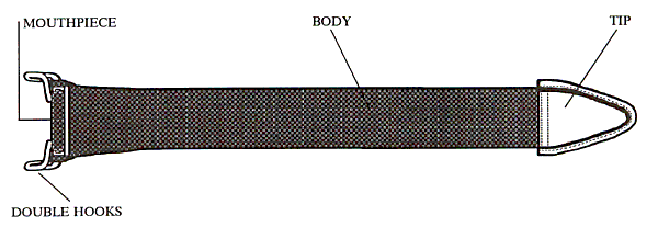
The parts of the scabbard are somewhat more consistent in nomenclature, probably since there are fewer of them. In general, the Scabbard consists of a Body, a belt attachment, a Mouthpiece or Throat, and a Tip.
The BODY is normally the part that encloses the length of the blade. It may be made of leather, metal, wood, or plastic depending on the model and time period.
On U.S. bayonets, the scabbard usually attaches to the belt or pack by a HOOK or DOUBLE HOOK. On many foreign bayonets and some few US, the belt attachment is by a separate piece of leather or web material which is normally called the FROG or HANGER.
The upper piece where the blade enters is normally called the MOUTHPIECE, or THROAT. This may be a separate piece such as on the Model 1917, or a piece inserted into the upper body, as on the Models 1892 and 1905. The name varies from scabbard to scabbard and by time period.
The bottom of the scabbard is usually called the TIP, but as shown in the drawings, is called the FERRULE on the Model 1917 and the KNOB on the Model 1892.

U.S. Model 1892 Krag Scabbard

U.S. Model 0f 1917 Scabbard